LTC1574CS(RevA) 查看數據表(PDF) - Linear Technology
零件编号
产品描述 (功能)
生产厂家
LTC1574CS
(Rev.:RevA)
(Rev.:RevA)
Linear Technology
LTC1574CS Datasheet PDF : 8 Pages
| |||
LTC1574
LTC1574-3.3/LTC1574-5
APPLICATIO S I FOR ATIO
inductor L1 is chosen for its excellent self-shielding prop-
erties. Open magnetic structures such as drum and rod
cores are to be avoided since they inject high flux levels
into their surroundings. This can become a major source
of noise in any converter circuit.
Design Example
As a design example, assume VIN = 9V (nominal),
VOUT = 5V and IOUT = 350mA maximum. The LTC1574-5
is used for this application with IPGM (Pin 6) connected to
VIN. The minimum value of L is determined by assuming
the LTC1574-5 is operating in continuous mode.
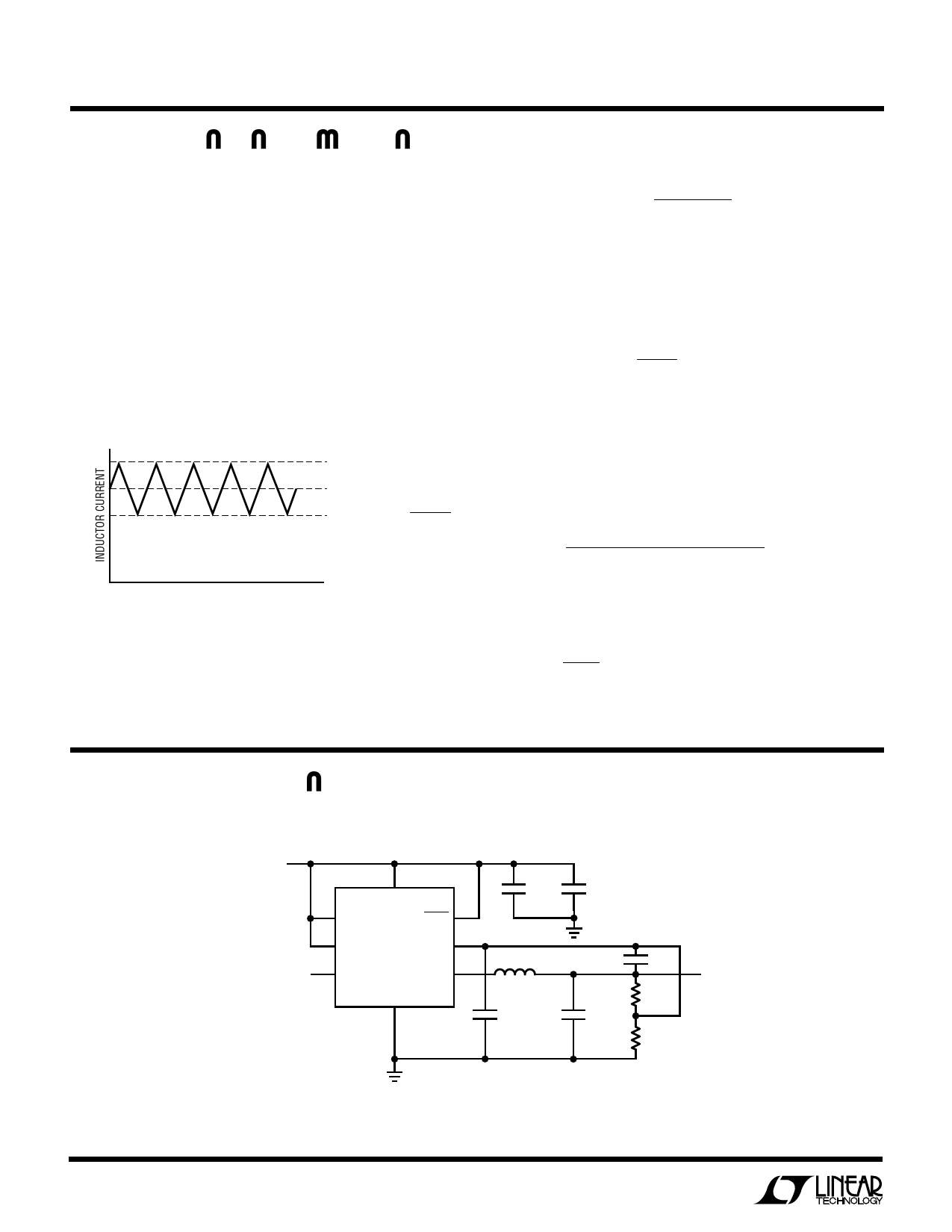
IPEAK
AVG CURRENT = IOUT
IV
= IPEAK + IV
2
= 350mA
TIME
1574 • F06
Figure 6. Continuous Inductor Current
With IOUT = 350mA and IPEAK = 0.6A (IPGM = VIN), IV = 0.1A.
The peak-to-peak ripple inductor current, IRIPPLE, is 0.5A
and is also equal to:
( ) IRIPPLE
=
4
•
10−6
VOUT +
L
VD
AP-P
Solving for L in the above equation and with VD = 0.5V,
L = 44µH. The next higher standard value of L is 50µH
(example: Coiltronics CTX50-4). The operating frequency,
ignoring voltage across diode VD is:
f
≈
2.5
•
105
1
−
VOUT
VIN
= 111kHz
With the value of L determined, the requirements for CIN
and COUT are calculated. For CIN, its RMS current rating
should be at least:
[ ( )]1/2
IOUT VOUT VIN − VOUT
IRMS =
VIN
= 174mA
( ) ARMS
For COUT, the RMS current rating should be at least:
( ) IRMS
≈
IPEAK
2
A RMS
= 300mA
Absolute Maximum Ratings and Latchup Prevention
The absolute maximum ratings specify that SW
(Pins 3, 14) can never exceed VIN (Pin 5) by more than
0.3V. Normally this situation should never occur. It could,
however, if the output is held up while the supply is pulled
down. A condition where this could potentially occur is
when a battery is supplying power to an LTC1574 regula-
tor and also to one or more loads in parallel with the the
regulator’s VIN. If the battery is disconnected while the
LTC1574 regulator is supplying a light load and one of the
parallel circuits is a heavy load, the input capacitor of the
LTC1574 regulator could be pulled down faster than the
output capacitor, causing the absolute maximum ratings
to be exceeded. The result is often a latchup which can be
destructive if VIN is reapplied. Battery disconnect is pos-
sible as a result of mechanical stress, bad battery contacts
or use of a lithium-ion battery with a built-in internal
disconnect. The user needs to assess his/her application
to determine whether this situation could occur. If so,
additional protection is necessary.
Prevention against latchup can be accomplished by
simply connecting a Schottky diode across the SW and
VIN pins as shown in Figure 7. The diode will normally be
reverse biased unless VIN is pulled below VOUT at which
time the diode will clamp the (VOUT – VIN) potential to less
than the 0.6V required for latchup. Note that a low
leakage Schottky should be used to minimize the effect
LATCHUP
PROTECTION
SCHOTTKY
VIN SW
LTC1574
VOUT
+
1574 F07
Figure 7. Preventing Absolute Maximum
Ratings from Being Exceeded
6
Share Link: 