STV2247H(2009) 查看數據表(PDF) - STMicroelectronics
零件编号
产品描述 (功能)
生产厂家
STV2247H Datasheet PDF : 86 Pages
| |||
STV224X, STV228X, STV223X - I²C BUS SPECIFICATIONS
5 I²C BUS SPECIFICATIONS
Data transfers follow the usual I²C format: after the start condition (S), a 7-bit slave address is sent, fol-
lowed by an eighth bit which is a data direction bit (W). An 8-bit sub-address is sent to select a register, fol-
lowed by an 8-bit data word to be included in the register.
The IC’s I²C bus decoder permits the automatic incrementation mode in write mode.
The circuit operates up to clock frequencies of 400 kHz.
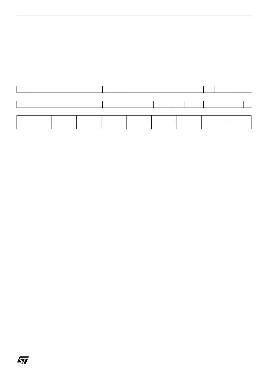
String Format
Write only mode (S = start condition, P = stop condition, A = acknowledge)
S
SLAVE ADDRESS
0A
SUB-ADDRESS
A DATA A P
Read only mode
S
SLAVE ADDRESS
1 A DATA 0 A DATA 1 A DATA 2 A DATA 3 A P
Slave Address
Address
A7
A6
A5
A4
A3
A2
A1
A0
) Value
1
0
0
0
1
0
1
X
t(s Write Address:
bsolete Product(s) - Obsolete Produc Read Address:
10001010
10001011
44/86
Share Link: 