LTC4098EPDC-1-PBF(RevB) View Datasheet(PDF) - Linear Technology
Part Name
Description
MFG CO.
LTC4098EPDC-1-PBF
(Rev.:RevB)
(Rev.:RevB)
Linear Technology
LTC4098EPDC-1-PBF Datasheet PDF : 32 Pages
| |||
LTC4098/LTC4098-1
OPERATION
MOSFET will be in full conduction. If additional conduc-
tance is needed, an external P-channel MOSFET transistor
may be added from BAT to VOUT. The IDGATE pin of the
LTC4098/LTC4098-1 drives the gate of the external P-chan-
nel MOSFET transistor for automatic ideal diode control.
The source of the external P-channel MOSFET should be
connected to VOUT and the drain should be connected to
BAT. Capable of driving a 1nF load, the IDGATE pin can
control an external P-channel MOSFET transistor having
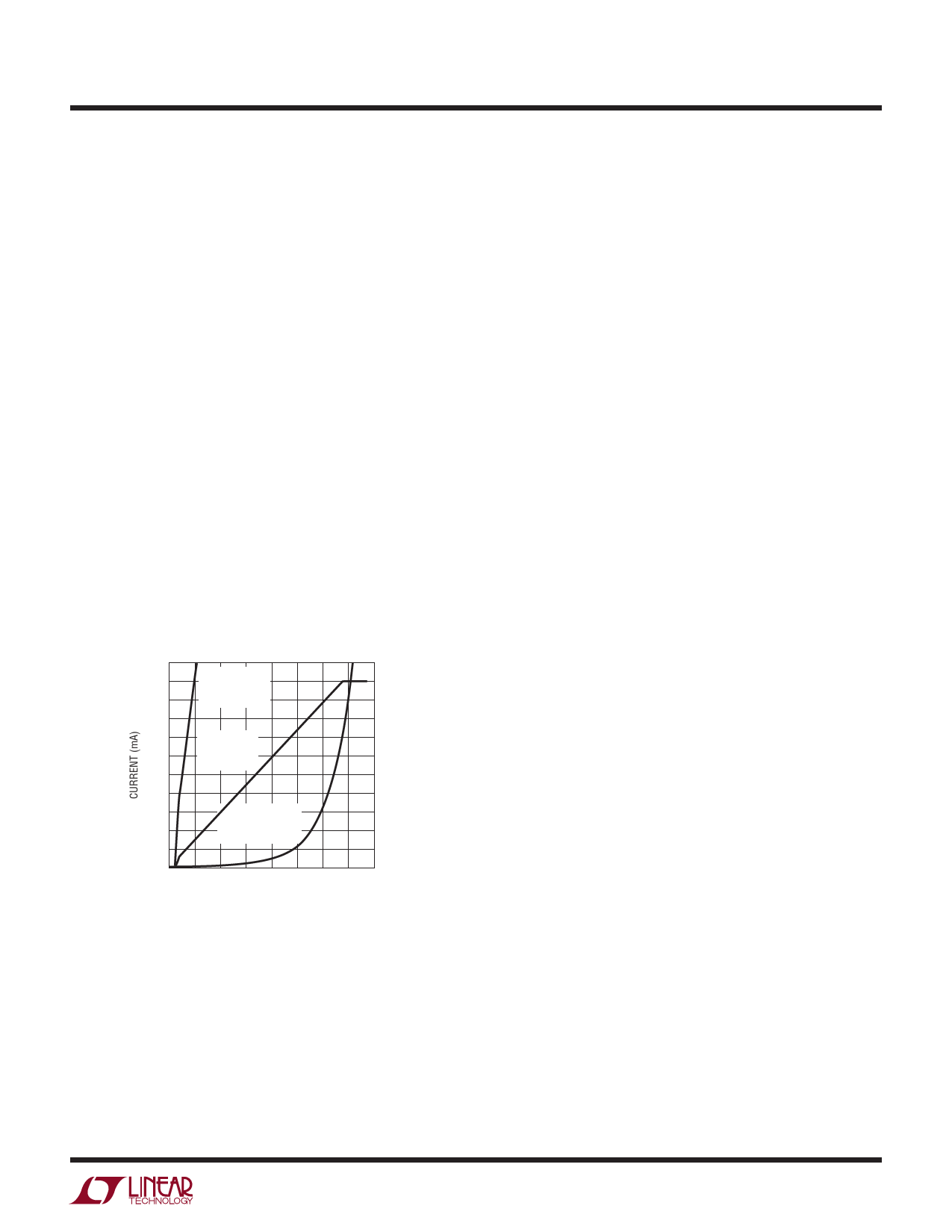
an on-resistance of 30mΩ or lower. Figure 5 shows the
decreased forward voltage compared to a conventional
Schottky diode.
Suspend LDO
The LTC4098/LTC4098-1 provide a small amount of power
to VOUT in suspend mode by including an LDO from VBUS to
VOUT. This LDO will prevent the battery from running down
when the portable product has access to a suspended USB
port. Regulating at 4.6V, this LDO only becomes active when
the switching converter is disabled. In accordance with the
USB specification, the input to the LDO is current limited so
2200
2000
1800
VISHAY Si2333
EXTERNAL
IDEAL DIODE
1600
1400
1200
1000
LTC4098/
LTC4098-1
IDEAL DIODE
800
600
ON
400
SEMICONDUCTOR
MBRM120LT3
200
0
0 60 120 180 240 300 360 420 480
FORWARD VOLTAGE (mV) (BAT – VOUT)
40981 F05
Figure 5. Ideal Diode V-I Characteristics
that it will not exceed the low power or high power suspend
specification. If the load on VOUT exceeds the suspend cur-
rent limit, the additional current will come from the battery
via the ideal diodes. The suspend LDO sends a scaled copy
of the VBUS current to the CLPROG pin, which will servo to
approximately 100mV in this mode. Thus, the high power
and low power suspend settings are related to the levels
programmed by the same resistor for 1x and 5x modes.
Battery Charger
The LTC4098/LTC4098-1 include a constant-current/con-
stant-voltage battery charger with automatic recharge,
automatic termination by safety timer, low voltage trickle
charging, bad cell detection and thermistor sensor input
for out-of-temperature charge pausing.
When a battery charge cycle begins, the battery charger
first determines if the battery is deeply discharged. If the
battery voltage is below VTRKL, typically 2.85V, an automatic
trickle charge feature sets the battery charge current to
10% of the programmed value. If the low voltage persists
for more than 1/2 hour, the battery charger automatically
terminates and indicates, via the CHRG pin, that the bat-
tery was unresponsive.
Once the battery voltage is above VTRKL, the charger begins
charging in full power constant-current mode. The current
delivered to the battery will try to reach 1030V/RPROG.
Depending on available input power and external load
conditions, the battery charger may or may not be able to
charge at the full programmed rate. The external load will
always be prioritized over the battery charge current. The
USB current limit programming will always be observed
and only additional power will be available to charge the
battery. When system loads are light, battery charge cur-
rent will be maximized.
40981fb
17
Share Link: 