CS5464-IS View Datasheet(PDF) - Cirrus Logic
Part Name
Description
MFG CO.
CS5464-IS Datasheet PDF : 46 Pages
| |||
CS5464
rent registers. The maximum pulse frequency from the
E1 pin is (MCLK/K)/2048.
5.5.4 Voltage Channel Sign Mode
Setting bits E3MODE[1:0] = 2 (10b) in the Operational
Mode Register outputs the sign of the voltage channel
on pin E3. Figure 8 illustrates the output format with volt-
age channel sign on E3.
E1
E2
E3
Figure 8. Voltage Channel Sign Pulse outputs
Output pin E3 is high when the line voltage is positive
and pin E3 is low when the line voltage is negative.
5.5.5 PFMON Output Mode
Setting bit E3MODE[1:0] = 1 (01b) in the Operational
Mode Register outputs the state of the PFMON compar-
ator on pin E3. Figure 9 illustrates the output format with
PFMON on E3.
E1
E2
E3
Above PFMON Threshold
Below PFMON Threshold
Figure 9. PFMON output to pin E3
When PFMON is greater than the threshold, pin E3 is
high and when PFMON is less than the threshold pin E3
is low.
5.5.6 Design Example
EXAMPLE #1:
The maximum rated levels for a power line meter are
250 V rms and 20 A rms. The required number of puls-
es-per-second on E1 is 100 pulses per second
(100 Hz), when the levels on the power line are
220 V rms and 15 A rms.
With a 10x gain on the voltage and current channel the
maximum input signal is 250 mVP. (See Section 5.1 An-
alog Inputs on page 17.) To prevent over-driving the
channel inputs, the maximum rated rms input levels will
register 0.6 in VRMS and IRMS by design. Therefore the
voltage level at the channel inputs will be 150 mV rms
when the maximum rated levels on the power lines are
250 V rms and 20 A rms.
Solving for PulseRateE using the transfer function:
PulseRate
=
-------------------F----R-----E----Q-----P------×----V-----R-----E----F----I--N-----2--------------------
VIN × VGAIN × IIN × IGAIN × PF
Therefore with PF = 1 and:
VIN = 220V × ((150mV) ⁄ (250V)) = 132mV
IIN = 15A × ((150mV) ⁄ (20A)) = 112.5mV
the pulse rate is:
PulseRate
=
-------------------1----0---0-----×-----2---.--5---2---------------------
0.132 × 10 × 0.1125 × 10
=
420.8754 H z
and the PulseRateE Register is set to:
PulseRateE
=
--------P----u---l-s---e---R----a---t-e---------
(MCLK ⁄ K) ⁄ 2048
=
0.2104377
with MCLK = 4.096 MHz and K = 1.
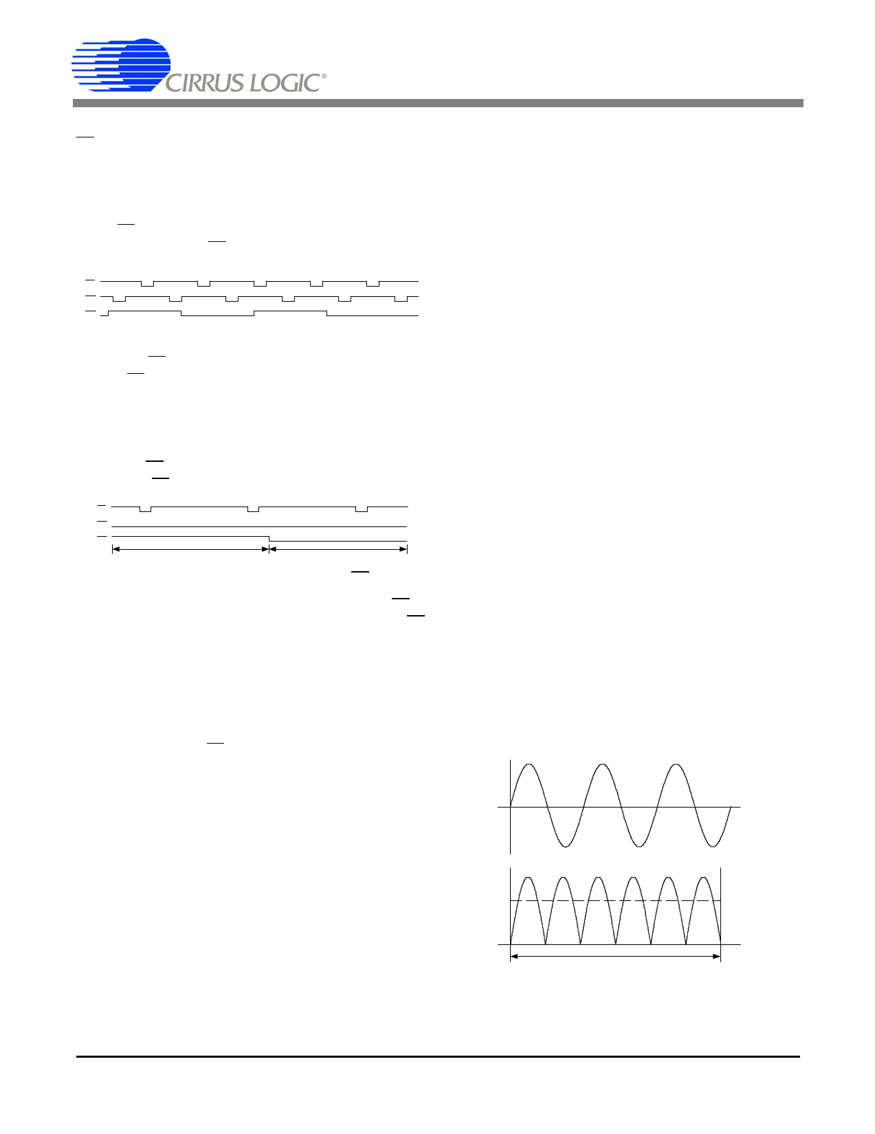
5.6 Sag and Fault Detect Feature
Status bit VSAG (V2SAG) and IFAULT (I2FAULT) in the
Status Register, indicates a sag occurred in the power
line voltage (voltage 2) and current (current 2), respec-
tively. For a sag condition to be identified, the absolute
value of the instantaneous voltage or current must be
less than the sag level for more than half of the sag du-
ration (see Figure 10).
To activate voltage sag detection, a voltage sag level
must be specified in the Voltage Sag Level Register
(VSAGlevel, V2SAGlevel), and a voltage sag duration
must be specified in the Voltage Sag Duration Register
(VSAGduration, V2SAGduration). To activate current fault
detection, a current sag level must be specified in the
Current Fault Level Register (ISAGlevel, I2SAGlevel), and
a current sag duration must be specified in the Current
Fault Duration Register (ISAGduration, I2SAGduration).
The voltage and current sag levels are specified as the
average of the absolute instantaneous voltage and cur-
rent, respectively. Voltage and current sag duration is
specified in terms of ADC cycles.
Level
Duration
Figure 10. Sag and Fault Detect
20
DS682PP1
Share Link: 